An Introduction to OpenGL - Getting Started
This article is a culmination of all the little notes I took while learning OpenGL over the last several months. It’s mostly stuff that I found difficult to research plus a little summary of the differences between OpenGL versions.
What a daunting task!
If you have any recommendations on how this could be more beginner-friendly please tell me.
Also thanks Gregg Tavares for pointing out my various errors!
Things I wish I knew when learning OpenGL
The most important thing a programmer should know before deciding whether to learn OpenGL is that OpenGL is very low level, poorly documented and extremely crufty. This is because it is an API specification and not a product library per-se. It is up to the many various vendors to implement the API spec as best they can.
In its various incarnations OpenGL spans almost 20 years and at least 7 major revisions, including the embedded versions. Anyone looking to learn to use OpenGL will face a constant battle with finding relevant documentation for their chosen version on their chosen platform with their chosen extensions.
The next thing to know about modern OpenGL is that these days it does very little legwork for you other than allowing you to run a program on the GPU. You will have to write the GPU shader programs that do everything from transforming your own application data into screen-space coordinates, to calculating the exact colour of every pixel on the screen incorporating lighting and shading algorithms that you implement yourself (fortunately linear algebra makes this stuff a lot simpler than it sounds!) So OpenGL will not do any inherently 3D stuff for you – most OpenGL commands and types are capable of describing 3D positions, directions and transformations but you have to do the grunt work yourself.
The third immediate concern – OpenGL does not work out of the box! An annoying truth is that OpenGL realistically requires supporting libraries in order to function, most importantly to create a context within which the rendering operations can work. It is very common to incorporating at least three libraries – one to generate a GL context into which you render, a matrix and vector manipulation library, and an extension loader for when you need a little more functionality than your platform provides.
So why would you even consider it?! Why would you write a series of articles on a technology that scares you so much? The reason it has kept its relevance is because OpenGL is the only low-level graphics API supported on pretty much all platforms you’d want to render graphics on. Because it is so very widely adopted it is still the defacto standard for developers wanting a powerful low-level intrinsics that work on multiple platforms.
If you are only targeting Windows you might consider DirectX. If you don’t need to interact directly with your shaders, and are happy to work at a higher level of abstraction and not with the GPU directly, perhaps a higher level graphics library such as Unity or UDK would work better for you.
So assuming you still want to start using OpenGL, this article might be helpful to you. My intention is to mention a lot of stuff I had to hunt around for that seemed pretty important to me while I was trying to learn it myself. I will not be doing a step-by-step guide to performing specific OpenGL tasks however – for a good getting started guide check out open.gl which is both modern and easy to follow.
To use OpenGL effectively I figure you’d need to understand:
- opening an OpenGL window (i.e., creating a context)
- the basics of rendering:
- primitives, vertices and fragments
- coordinate systems:
- built-in normalised device coordinates (NDC) and clip coordinates
- 3D model, view and perspective coordinates
- shaders and the render pipeline (how data gets from your app to the screen):
- vertex and fragment shaders
- passing uniforms and attributes into the pipeline
- vertex buffers (VBOs)
- passing varying data from the vertex shader to the fragment shader
- the fixed-function pipeline (now deprecated)
- linear algebra (the magical language of graphics programming)
- a rundown on all the different major OpenGL versions
- major challenges that you certainly will face moving forward
I’ll leave more advanced core concepts such as framebuffers and textures for a later article.
Starting a new project
I suppose this is the most important thing to a lot of people, so I’ll show how I bootstrap a new OpenGL project. I haven’t been at it long so take it with a grain of salt, but I tried to focus on building a cross-platform solution.
I generally depend on four libraries. Although technically you could get away without any supporting libraries, these save a lot of time and effort. The libraries are:
- Google’s ANGLE project provides an OpenGL ES 2.0 (soon 3.0) driver library for Windows that wraps Direct3D. This is useful so you don’t have to depend on the user downloading the OpenGL drivers for their graphics card on Windows.
- GLFW to create a window and otherwise interact with the OS and other devices. Many people prefer SDL2 or GLUT. Alternatively you could use the standard low-level supporting libraries supported by your operating system – WGL, GLX or EGL.
- GLM is a widely used vector and matrix library. It’s particularly nice because it mirrors GLSL standard types and operations as much as possible, so hopefully there’s some learning synergies there. I have tried using Eigen which is more of a general linear algebra library focusing on performance, but it has a lot of limitations on how you can use (passing or storing types by value is complicated) it because it uses low-level processor vector operations under the covers. Of course you could always write your own matrix classes, but it’s a pretty big task.
- GLEW is a commonly used extension loader. Unfortunately extension loaders in general don’t seem to work with ANGLE so I haven’t used it much. glbinding and glLoadGen are both code generators that create loaders for specific target versions of OpenGL. These don’t seem to be able to target OpenGL ES versions however.
I have created a simple GL application on GitHub that I intended to be used as a starting point for OpenGL ES 2 experimentation. It should work on Windows, Linux and OSX, and the only external dependency should be CMake which is pretty easy to install. Then, hopefully, getting it running is a matter of (depending on your platform of choice):
1 2 3 4 5 6 | |
Alternatively you could try copying my sample GL HTML page and copy the webgl-utils.js file into a subdirectory called ‘js’ under that. Run the HTML file in your browser and you’ll have a WebGL app!
Understanding the OpenGL API
Note: I’m using OpenGL ES 2 GLSL syntax in my examples because I believe that’s probably got the broadest platform support, and is most similar to WebGL. The concepts are the same for later versions, aside from the syntactic differences. As I am focusing on explaining core concepts only OpenGL ES 2 should be fine for my purposes.
Take a moment to read some OpenGL specifications – they are probably easier to understand than you’d think. Here’s the OpenGL ES 2.0 Spec if you want a definitive source for all this stuff.
I will probably mention the Khronos Group a lot throughout this article. The Khronos Group is a consortium of companies such as Sun Microsystems, NVidia and Silicon Graphics who work on standardising graphics APIs, including OpenGL. Part of their OpenGL standardisation process is to provide reference interfaces (header files) for each version of the API that vendor implementations should conform to.
Here’s a bit of a glossary of terms and concepts that are necessary to become familiar with in order to be an effective OpenGL programmer.
The OpenGL API – commands, enums and objects
The OpenGL API consists entirely of commands (e.g., glDrawElements()), enums (e.g., GL_COLOR_BUFFER_BIT) and, conceptually, objects.
The commands and enums are described in the specification but can also be browsed on the Khronos API header files – have a look at GLES2/gl2.h for the standard GLES2 header. Most vendor implementations use these exact files as the entry point for their libraries.
OpenGL objects are the conceptual entities you create using the API, such as vertex buffers (VBOs), vertex arrays (VAOs), shaders, programs, textures and framebuffers. OpenGL has commands to create, bind and delete each of the different types of objects. Note that the objects you create are only valid with the context that was active when you created them!
OpenGL commands that operate on OpenGL objects require those objects to be bound. For example when you call glDrawElements() you don’t pass the program, the target framebuffer or the vertex or index buffer IDs to the function, it just operates on whichever program, framebuffer and vertex buffers are currently bound (through the glUseProgram(), glBindFramebuffer() and glBindBuffer() commands.) Many people feel this is a confusing and error-prone way to do things; it means that if you call some library or function that uses OpenGL there is no way to determine whether it has modified the current context in any way, so you have to re-bind all your stuff. It’s unfortunate but that’s the API we are stuck with :(
Note: it is interesting to note that the glCreate-type functions don’t actually create or allocate anything! They give you back a free handle, but that handle isn’t actually allocated until it is bound. This means that technically you’re free to keep track of these IDs yourself and allocate them according to whatever scheme you most desire, though I’m not sure why you’d do that.
OpenGL context
Here I’ll describe the concepts involved in creating and using OpenGL contexts. For a more tutorial-type approach have a look at this guide that shows how to use several different popular context management libraries.
The context encapsulates the rendering view, its rendering settings and which OpenGL objects are currently active (such as which shader will be invoked during rendering). When starting your application you will need to create a context and set the capabilities you want the driver will use while rendering, such as whether the renderer will perform scissor, stencil, depth or alpha testing, how the renderer will blend fragments into final pixel colours and what part of the window to render into (the viewport). Contexts are not thread-safe (unfortunately!) and are essentially global in scope (even more unfortunately!) and are the cause of most of the grief people have with OpenGL.
You should avoid querying the state of the context too much if possible (i.e., querying information about bound objects, or even constantly querying error state) – it is apparently quite slow. You should also avoid accessing context from multiple different threads. I believe you are supposed to create separate contexts in each thread you wish to render from, or more preferably not render from multiple threads at all.
It is also possible to create a shared context where objects created on one context are available in another. This can be tricky so proceed with caution – for example, according to the spec shared contexts may not share framebuffer objects for some reason. I found that out the hard way.
Unfortunately the creation of an OpenGL context is not defined by the OpenGL spec. If you want to create one you’ll either have to look up how to do this on your platform of choice (for example Windows provides WGL, while OSX and Linux systems use GLX) or use another third-party library that does this for you (I like GLFW, but SDL2 is very popular, and some people still use the older GLUT.) These libraries often give you access to keyboard and mouse input as well as various other utilities you might need when making your app (such as buffer swapping, text, audio and the like.)
Below is a simple example of creating a context using GLFW in C or C++. For a line-by-line explanation of this see the official GLFW docs.
1 2 3 4 5 6 7 8 9 10 11 12 13 14 15 16 17 18 19 20 21 22 23 24 25 26 27 28 29 30 31 32 33 34 35 36 37 38 39 40 41 42 43 44 45 46 47 48 49 50 51 52 53 54 55 56 | |
Most OpenGL context management libraries are very similar in usage to this.
Primitives, Vertices and Fragments
Each time you call an OpenGL drawing function you are drawing a primitive. You can think of a primitive as a shape of some kind that can be either 2D or 3D and rendered as a collection of points, lines or triangles.
You specify the primitive type you want to draw when invoking glDrawElements() or glDrawArrays(). Among the valid types are:
GL_TRIANGLES, which uses each 3 vectors to create a triangle. If you provide 9 vertices you will draw 3 triangles.GL_TRIANGLE_STRIPis more complicated in that it will use each set of 3 consecutive vertices to draw a triangle. In other words if you supply 4 vertices it will draw 2 triangles – one from v0, v1 and v2, another from v2, v1, v3. Notice that the first two vertices of every second triangle are re-ordered – this is to ensure that the triangles all face the same direction, as triangle direction is derived from which direction the triangle’s vertices appear to be counter-clockwise in order (relevant if face culling is enabled.)GL_POINTS, which renders unconnected dots. You can control the size of the points by calling theglPointSize()command in desktop GL or by setting thegl_PointSizeGLSL variable in OpenGL ES. You can also apply a texture to the point to render more complex particles (the GPU passes your fragment agl_PointCoordvariable to indicate which texture UV coordinates you should render.)GL_LINESis useful for quickly drawing a wireframe of your model.- there are also
GL_LINE_STRIP,GL_LINE_LOOP,GL_TRIANGLE_FAN,GL_QUADS,GL_QUAD_STRIPandGL_POLYGON.
You will describe your primitives as collections of vertices. These vertices are passed to the GPU and it then transforms them to triangles then rasterises those triangles into fragments. These fragments may be filtered, blended and anti-aliased and ultimately may be drawn as pixels on your screen. So technically fragments are not pixels.
Coordinate systems
The OpenGL coordinate system is simple but requires some explanation – put simply, the range of visible coordinates within the viewport goes from -1.0 to 1.0 in the X, Y and Z directions. This coordinate space is known as normalized device coordinates or NDC, and anything falling outside of this range will not be rendered. The X and Y coordinates describe the horizontal and vertical component of the pixel (-1, -1 corresponds with the bottom left corner of the viewport) and the Z axis is the depth component that is used for depth testing (if enabled.) By default the NDC Z coordinates move away from the viewer, so +Z is into the screen.
. By convention XYZ shown as RGB\"")
But you won’t be using NDC directly – you will be rendering your primitives in what is known as clip coordinates, which are very similar to NDC except with a 4th dimension (x, y, z and w). You might be somewhat confused when you write your vertex shader, when setting the mandatory gl_Position variable with the vertex coordinates (described later) you’ll notice it is a vec4. What’s the 4th dimension for? It turns out the 4th dimension w is used for perspective division, which is super useful for 3D graphics but useless for 2D. For now you just have to know that when the GPU transforms from clip coordinates to NDC it calculates something like this: ndc_coords = clip_coords.xyz / clip_coords.w. So if rendering 2D stuff to the screen just set gl_Position.w to 1.0.
When programming in 2D you may choose to draw all your primitives using these NDC coordinates to avoid having to convert between coordinate spaces at all. The samples in this article draw primitives using normalised device coordinates directly.
3D coordinate systems are more complicated and I will discuss them in depth in a later article. For now it is interesting to note two things: first, by convention OpenGL coordinate systems other than NDC generally have the Z axis moving towards the viewer, so the negative Z axis goes into the screen.
Secondly, when rendering 3D primitives the verticies that describe the primitive are usually transformed in between a well defined sequence of coordinate spaces. The coordinates in the model’s local model space are first moved to world space where their position and orientation is given relative to all other objects in a scene (the same model may be used many times in the one scene, but each will look different if they have different model space transformations.) Then the coordinates are transformed to view space where their position and orientation are relative to the viewer’s eye. Then they are transformed into clip coordinates and finally NDC as before. I hope to go into more detail on this process in a later article – I just wanted to list the terms here for completeness.
One final thing I will mention about 3D coordinates is that it is common to specify 3D positions, directions and transformations using 4 dimensional vectors and matricies. I won’t go into it now but it is very useful to remember that positional coordinates generally have a 4th dimension w set to 1.0 and directions generally have w set to 0. This makes the linear algebra work out nicely when multiplying against transformation matricies as the 4th dimension in the vector usually controls the translation factor of the transformation, which is not relevant for directions (i.e., a ‘north’ pointing vector is stil pointing north no matter where the vector is located in space.)
Shaders and the render pipeline
Every time you call an OpenGL draw operation (the glDrawArrays() or glDrawElements() commands) you invoke the entire render pipeline. This is when the GPU passes the verticies in your primitives to your vertex shader, clips the resulting coordinates, generates triangles from the vertices, rasterises them into fragments, passes those fragments to your fragment shader then tests visibility, blends and dithers those fragments into pixels on your screen (or some other framebuffer.)
The difference between glDrawArrays() and glDrawElements() is in how the GPU knows which vertices to use when transforming your vertices into triangles. glDrawArrays() is simpler in that it builds triangles using the vertices in their given order – in a GL_TRIANGLES primitive, triangle T0 will be built from vertices V0, V1 and V2, triangle T1 built from V3, V4, V5 and so on.
glDrawElements() is more complex but often more performant. Instead of using the vertex data strictly in the order you declared them, it uses a separate buffer called the index buffer (also known as the element buffer) to determine which vertices to use in which triangles. This is great because it allows you to reuse vertices to create multiple triangles – an index buffer of [0, 1, 2, 2, 1, 3, 1, 0, 4] will construct 3 triangles from only 5 vertices! The first triangle will be using v0, v1 and v2, the second using v2, v1, v3 and the third using v1, v0 and v4.
Note: Vertex buffers are bound by invoking glBindBuffer(GL_ARRAY_BUFFER, my_buff_loc) and index buffers are bound with glBindBuffer(GL_ELEMENT_ARRAY_BUFFER, my_buff_loc). Don’t ask me about the names.
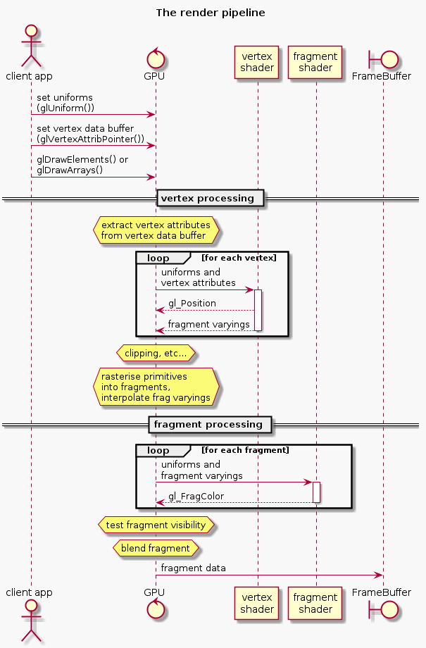
Pipeline summary
To draw a primitive, the GPU first needs your vertex data. The GPU will decode your vertex data to extract vertex attributes and pass those into your vertex shader once for each vertex. Your vertex shader is expected to output clip coordinates for that vertex so the GPU knows where on the screen to show it (if at all,) and information that the GPU should pass on to your fragment shader for fragments derived from this vertex.
Once the GPU has processed all vertices the GPU can clip the vertices to within the NDC area only, it transforms those vertices into triangles and then rasterises the triangles into fragments which sort-of represent the pixels of the primitive being drawn. The GPU will then call your fragment shader for each fragment, passing it the relevant output data of your vertex shader. Your fragment shader is expected to output a colour and optionally a new depth-value for the fragment.
The GPU then processes, blends and dithers the fragments to the output framebuffer, as described under how the GPU writes fragments to the framebuffer a few pages down.
You invoke the rendering pipeline by calling either the glDrawArrays() or glDrawElements() commands (or one of their variations.) Unless you’re using the fixed function pipeline you’ll have to have a shader program bound so the GPU knows which vertex shader and fragment shader to invoke. You will also have to specify the vertex data (the vertex positions and perhaps other information such as the vertex normals and colours) of the primitive you are rendering. The ‘basic shader program’ a few pages down shows one way to do both of these things.
Once again, if you want more details on how this works have a look at the specs, like the OpenGL ES 2.0 Spec.
Passing data to the GPU – uniforms, attributes and varyings
There are two ways your application can pass data to your shaders – uniforms that are set only once per glDraw* call and and attributes that may be different per-vertex. In addition, fragment shaders receive per-fragment input derived from the output of the vertex shader in varyings (see the rendering pipeline diagram above.)
Sending uniform data to the GPU
A uniform represents a variable that remains the same for the rendering of an entire primitive. This might be something like the object material or the position of the sun. The pattern for setting a uniform is to first get a handle to the uniform with glGetUniformLocation(my_program, "my_uniform"). Pass this handle to the glUniform* functions to set the uniform (for example glUniform3f() will set a uniform of type vec3 in your shader.) Setting a uniform will make it available in any of the shaders in the bound program that are want to use it.
In the code example a few pages down you can see how the unifrom data is bound and updated:
1 2 | |
Uniforms may also be structures and arrays – the syntax to declare and use structs and arrays in GLSL (the shader code) is very similar to C, but setting them from the client application is a little tricky.
To set uniform values in a structure: you essentially treat the variable as if it is in the namespace of the structure name. E.g., if the shader contains the code struct Point { float x; float y; }; uniform Point p1; you can access p1.x with exactly that syntax: auto u_p1x = glGetUniformLocation(my_program, "p1.x").
To set uniform values in an array: you access the specific array element using standard C syntax. If the shader contains the code float xs[10]; you can get the location of a particluar element of xs with auto u_xs = glGetUniformLocation(my_program, "xs[0]"). You can use this uniform location to either set a single element using glUniform*() or set a number of the elements using glUniform*v().
Note: that you cannot apply offsets to the returned uniform location to access specific array elements – in the above example, I cannot call glUniform1f(u_xs + 2, 1.) as that could be the location of a totally different uniform. In this case you would either have to find the location of the element you want to access directly (in this case glGetUniformLocation(my_program, "xs[2]")) or set multiple elements (using glUniform*v()) in the array starting from the index we retrieved.
Sending vertex attribute data to the GPU
An attribute represents data related to the current vertex being processed. You specify where the GPU can find vertex data by calling the glVertexAttribPointer* functions for each vertex attribute in your vertex shader. This process is very different to specifying uniforms!
The standard form for using a vertex attribute is something like:
1 2 3 4 5 6 7 8 9 10 11 12 13 | |
The above code snippet illustrates how to passing a raw pointer to your vertex data to the GPU. This is not the usual case, because quite often your buffered data will interleave more than one attribute’s worth of information (such as normals, vertex colours etc.) Usually you will create a vertex buffer object (VBO) and use glVertexAttribPointer() to dictate how the GPU should extract the vertex info from that.
vertex buffer objects are created, bound and destroyed like any other OpenGL object. You specify the data to buffer by calling the glBindBuffer() command with a pointer to the buffer. While this buffer is bound, any calls to glVertexAttribPointer() with a non-pointer in the final parameter will implicitly be referring to the bound buffer, using the final parameter instead as an offset into the buffer where the data may be found. This is necessary for interleaving vertex data in the same buffer.
Having a single buffer with different types of vertex information interleaved is very common. Your two tools for describing how this buffer data is formatted are the above-mentioned offset parameter and the stride parameter. While the offset describes the starting byte of an attribute in the buffer, the stride describes the total distance (in bytes!) between the start of that attribute and the start of the next instance of that attribute. A stride of 0 is considered special – it is used if the attribute is ‘tightly packed’, meaning the buffer contains only that attribute with no space between them.
This is best illustrated with an example:
1 2 3 4 5 6 7 8 9 10 11 12 13 | |
Note: in OpenGL 3.0 and above you will want to use vertex array objects (VAOs) to speed up your rendering process. A VAO offers you shorthand for binding vertex bufffers and the related vertex attributes for those buffers. This means that glBindVertexArray() can replace a number of glBindBuffer() and glEnableVertexAttribArray() commands.
The pattern for using this is:
1 2 3 4 5 6 7 8 9 10 11 12 13 | |
I won’t be illustrating those here because I am focusing on OpenGL ES 2.0 for this article.
Sending per-fragment varyings to the fragment shader
Varyings are per-fragment data the fragment shader uses to calculate the output colour of a fragment. Examples of this might be the normal of the surface at that point, or the material colour interpolated from the material colours of the surrounding vertices. A 3D program will often use this information along with the location of the sun (passed through a uniform) in its lighting calculations – a fragment on a surface directly facing a light source will have a brighter colour than one not.
The calculation of what value is passed into a varying is a little bit tricky. Fragment shaders get their per-fragment input indirectly from the vertex shaders through variables called varyings. Of course for any three vertices forming a triangle you could have hundreds of fragments, so the GPU takes the varyings coming out of the vertex shader for each vertex influencing a fragment and interpolates them before passing them into the fragment shader.
The Vertex Shader
Below is a simple vertex shader that expects two input variables from the application: the uniform time and the vertex attribute vert_position.
1 2 3 4 5 6 7 8 9 10 11 12 13 14 15 | |
Note: GLSL (the shader language) allows the specification of precision for floating-point values, including all vec and mat types. Some versions of GLSL (at least GLSL ES) require variable precisions to be specified in all declarations and parameter lists (I have omitted these for brevity in my examples.) Valid precision values are lowp, mediump and highp. In general mediump is what you want, although for colours you can use lowp without any problems.
The Fragment Shader
The fragment shader captures all the logic required to determine the colour of a fragment. This might be as simple as just returning a uniform RGBA value or might involve complex 3D shading calculations incorporating a number of light sources and shadow maps. I will explore the 3D stuff in a later article.
A simple fragment shader that works with the above vertex shader might look like this:
1 2 3 4 5 6 7 8 9 | |
Note that the varying variables are not passed directly from the vertex shader but is actually interpolated from the results of all vertex shader invocations for the vertices surrounding this fragment. This means that, for example, colour gradients look smooth between vertices.
How the GPU writes fragments to the FrameBuffer
In this context the framebuffer is the rendering target, which is usually either the viewport or a texture. (Framebuffers are also used for other purposes such as combining multiple rendering passes that I will go into in a later article.) When the GPU has collected all the fragments it is going to render, it goes through a series of per-fragment operations to determine what gets written to the framebuffer.
First the GPU checks to ensure this bit of the viewport is actually owned by this framebuffer, because is possible to have one viewport obscuring another. Next the fragment is tested against the scissor test region, the stencil buffer, then the depth buffer, if those capabilities are enabled in current context. If a fragment fails one of these tests it is discarded. Then the GPU performs a blending operation if enabled on the context, blending the fragment against what is read from the framebuffer before the render operation began. The resultant fragment is finally written to the framebuffer. Furthermore, if the framebuffer has multisampling enabled (for anti-aliasing) it may merge multiple fragment colours (or samples as they are called now) into a single pixel.
Basic shader program example
The partial application code below shows a basic vertex shader, fragment shader being invoked to render a square in the middle of the window.
1 2 3 4 5 6 7 8 9 10 11 12 13 14 15 16 17 18 19 20 21 22 23 24 25 26 27 28 29 30 31 32 33 34 35 36 37 38 39 40 41 42 43 44 45 46 47 48 49 50 51 52 53 54 55 56 57 58 59 60 61 62 63 64 65 66 67 68 69 | |
This should look something like this:
click here to open in a separate window
Immediate mode and the fixed function pipeline
I discuss this more when discussing the different OpenGL versions below, but OpenGL 1 was much simpler to use than later versions, though much less powerful. OpenGL 1 operated using a fixed-function pipeline using an immediate mode API, where the programmer not only describes high-level primitives’ individual vertices but also describe the lighting model to use, define several lights and set up materials to use during rendering. Retained mode allows all of this functionality to be executed on a shader program, which is written by the developer but run on the GPU directly. This is much more performant but requires a lot of extra work on the part of the developer.
The term immediate mode means that the drawing operations are explicitly executed in your client application each frame, which is considered slower because it ties the client application logic too closely with the GPU rendering operations, so the GPU is not able to make as many optimisations as it would if the instructions were on the GPU itself (retained mode.)
Linear algebra (magic!)
Linear algebra is the language of graphics programming. You need to learn some basics if you’re going to tackle this stuff. I won’t go into what a vector or matrix is here but you will have to learn the basics of their form and function if you don’t already know them.
The most basic understanding you should have is that vectors are usually used to describe coordinates in space and directions, and matricies are used to describe transformations (translation, scale, rotation, shear etc) to those vectors. Another thing to note is that a single matrix may represent an accumulation of many different transformations performed in sequence, so if I said (in pseudo-code) auto m = translate * scale * rotate, then any time I multiply m by a vector it will have the same effect as performing all of those transformations at once – amazing!
Once again, the OpenGL API does not help you in dealing with matricies or vectors, but there is a great supporting library that does – GLM.
There are two ways the elements in a matrix may be stored – OpenGL programmers often use column-major matrix layouts. This is a convention only, but is generally used in the official documentation and in OpenGL support libraries such as GLM. The reason this is important is that unlike scalar multiplication, matrix multiplication is not commutative, meaning A * B does not equal B * A. The main impact of using column-major vs row-major matricies is the order of multiplications must be reversed to have the same effect. In column-major (the most usual) you would accumulate your transformations to the left, so if you want to first rotate (R) then scale (S) then translate (T) last, you would execute T * S * R. A more common example would be when calculating the model view projection matrix it would be accumulated as mat4 mvp = P * V * M. When calculating this with a row-major library you would be expected to accumulate it as mat4 mvp = M * V * P. Converting a matrix to or from column-major to row-major is known as transposing the matrix.
A common term in linear algebra is the identity matrix. This is a matrix I where multiplying it with another matrix A gives that matrix (I * A = A.) It is easily recognisable as it is entirely made of 0s with 1s on the diagonal.
Another generally useful matrix operation is the inverse of a matrix. The inverse of a matrix A is the matrix required to multiply with A so that the result is the identity matrix. In other words, Ai * A = I. This is useful when rolling back a matrix multiplication. If you have the model view projection matrix mat4 mvp = proj * view * model, you can find the model view matrix by calculating the inverse projection inv_proj and calculating: mat4 mv = inv_proj * mvp.
Vector operations are even more interesting. A few things I want to point out here are dot product, cross product and the difference between positional coordinates and directional coordinates.
The dot product operation (sometimes known as the inner product) is used for many purposes; the dot product of two vectors A and B is a scalar (not a vector) number that is the sum of the products of their components (e.g., auto a_dot_b = A.x * B.x + A.y * B.y + A.z * B.z). It turns out that this simple formula gives you the cosine of the angle between those vectors multiplied by their magnitudes (|A||B|cos(Ɵ)), which is really useful because:
- if the vectors are unit vectors (they each have magnitude of 1) the dot product will just give you
cos(Ɵ)which is a number between 0 and 1, where 0 implies that they are perpendicular to each other (at 90 degrees) and 1 implies they are parallel. This is great for calculating how much light should bounce off a surface if the light direction is one vector and the surface normal is the other. - if the vectors are both unit vectors you can inverse cos the dot product to find the angle between the vectors (
auto angle = acos(dot(A, B))) - you can find the projection of vector A onto vector B by finding the dot product of A and B then dividing the result by the length of A.
- calculating the dot product of a vector with itself will give you the distance squared. If you are checking to see which vector is longer, you can just compare their squared distances (saving you a square root operation)
The cross product is another simple formula that gives you a vector that is perpendicular to two given vectors. In other words, if you have vectors A and B that both lie along the same surface, calculating cross(A, B) will give a vector that represents the normal to that surface. This normal vector will also follow the right-hand rule as pictured below (Note: you will usually want to normalise your normal before using it, so lighting calculations can dot product them straight out of the box!)

OpenGL versions and extensions
A constant frustration when reading documentation and code examples is that OpenGL 1.0 is worlds apart from OpenGL 2.0. Many of us would have been well served if they had given it a totally different name, so different are the products!
OpenGL 1 functions in what is now called immediate mode and is considered deprecated. In this version the programmer describes the scene lights, materials and fog, then notifies the driver of each polygon explicitly. The driver would then render the scene using its own internal lighting model using the described lights and materials. This is called the fixed function pipeline.
1 2 3 4 5 6 7 8 9 10 11 12 13 14 15 16 17 | |
OpenGL 2 introduced shaders, yet still provided compatability with the above described model. Shaders had access to the state declared in the fixed function pipeline through standard global variables (such as the gl_LightSource[] array and the gl_FrontMaterial variable sent from the client and the gl_ModelViewProjection matrix which was generated by the driver.) The vertex shader can invoke the standard fixed-function pipeline functionality by callling gl_Position = ftransform();.
OpenGL 3 completely deprecated the immediate mode fixed-function pipeline. Of course this introduced backwards-compatability issues so they also introduced several profiles to allow backward compatability to be optionally compiled in. The compatability profile can be requested to enable deprecated features, while the core profile disallows the use of these features.
Since OpenGL 2 however there have been no truly large architectural changes (unfortunately.) Changes have focused around adding features (new types of shaders, for example) to provide better performance and more generally useful aspects of existing functionality. This is a shame because there are still a lot of problems with OpenGL that many developers want addressed – the original goal of OpenGL 3 was to include massive refactorings to remove all the global state (more on this later) but vendors objected so strenuously that this work was put off until GLNext which is now known as Vulkan.
OpenGL shaders are written in their own language – GLSL. GLSL has its own varied syntax between versions, and to make things even more complicated they support the notion of extensions. The best bet is to decide on which version of OpenGL you will be learning and learn the GLSL appropriate to that version. They are all quite similar in form but are syntactically incompatible with each other.
Some mention should be made regarding extensions. Extensions are often touted as a great feature in OpenGL not available in other graphics libraries such as DirectX. New commands and enumerations are often added to the OpenGL API by vendors as extensions, and then if this functionality proves popular it becomes formalised as part of the API in a later version.
Each OpenGL version has a known set of extensions. These can be browsed in the Khronos reference implementations – for example the OpenGL ES 2 extensions are in the GLES2/gl2ext.h header file. There are idiomatic ways to detect support for and load these extensions using system calls but most people use an extension loader of some type. A very popular extension loader is the OpenGL Extension Wrangler Library (also known as GLEW.)
If you want some functionality not natively available in your chosen version of the OpenGL API you will often find an extension that provides that functionality. The problem is, extensions are not supported uniformly on all platforms with all drivers, so quite often you’ll have to work around the missing functionality in some platform anyway. This severely limits the usefulness of extensions, and in general you should try to do without them if possible.
I personally do use a few extensions in a few circumstances: either to get around eccentricities of a particular platform (e.g., some Windows platforms use BGRA instead of RGBA framebuffer formats, which are only available through the GL_EXT_texture_format_BGRA8888 extension) or if I have through experimentation determined that an extension is very broadly supported.
Here’s a quick summary of what I understand of the different OpenGL versions:
OpenGL 1 – high level and slow but simple
- Immediate mode only (fixed function pipeline)
- no shaders
- a lot of people still use this when demonstrating functionality
- only version natively supported by Windows
OpenGL 2 – shaders run on the GPU
- first shader-based version
- vertex and fragment shaders
- still have access to the fixed function pipeline – even within shaders
OpenGL 3 – a controversial release
- framebuffers for rendering to non-screen targets (e.g., render to a texture)
- vertex array objects (VAOs) allow great performance boosts by quickly binding and unbinding whole groups of buffers and attribute bindings
- geometry shaders (modify/extend geometry of primitives)
- significant (breaking!) changes to GLSL shader language
- deprecated most 1.0 functionality (immediate mode stuff) introducing compatability and core modes
- compatability mode gives access to the old fixed function pipeline
- core mode does not
OpenGL 4 – modernisation, performance and professional enhancements
- OpenGL 4.0 goal was to achieve parity with Direct3D 11
- OpenGL 4.5 goal was to achieve parity with Direct3D 12
- tesselation shaders introduce extra polygons for ‘denser’ meshes with smoother curves
- compute shaders for using the GPU for non-graphics computations (GPGPU stuff)
- GPGPU compute shader uses SPIR – an intermediate language based on LLVM
- Direct State Access – mitigate long-standing architectural problems with immediate mode
- modern OSX supports up to OpenGL 4.1
OpenGL ES – simplified for embedded systems
- OpenGL ES 1.0 based on OpenGL 1.3
- OpenGL ES 1.1 based on OpenGL 1.5
- OpenGL ES 2.0 based on OpenGL 2.0
- WebGL is based on OpenGL ES 2.0
- Google ANGLE project provides OpenGL ES 2.0 support on Windows (wraps DirectX API)
- OpenGL ES 3.0 full subset of OpenGL 4.3
- GLSL ES 3.0 based on GLSL 3.3
- similar to OpenGL 3 but without geometry shaders
- supported by modern iOS and Android devices
- experimental support in Google ANGLE project
WebGL
- based on OpenGL ES 2.0
- I don’t know much about this yet, but WebGL Fundamentals is a great resource
Vulkan – GLNext, lots of hype but not much information yet
- get away from immediate mode single-threaded global state context heritage
- allow shaders to be written in a variety of languages
- http://arstechnica.com/gadgets/2015/03/khronos-unveils-vulkan-opengl-built-for-modern-systems/
I have chosen to do most of my experimentation in OpenGL ES 2. This should give me the broadest platform availability as well as being compatible with WebGL for web demonstrations. I have resorted to using a few extensions that are supported on the platforms I use where necessary (e.g., to get anti aliasing), though I try to avoid this where possible.
Challenges you will face
- Having to learn support libraries in addition to the OpenGL API
- Cross platform support is difficult as many features are not uniformly supported
- Debugging GL state in different platforms – OpenGL debugging tools are not great, and there are none that work cross-platform
- Multithreading correctly is extremely difficult – if possible just do all your rendering on one thread!
- Managing extensions can be a pain in the ass
- State management – OpenGL uses global state, so it is impossible to write optimal abstractions because cannot encapsulate state, and state querying is prohibitively expensive. So you end up redundantly setting state that has often already been set.
- lots of problems: http://richg42.blogspot.jp/2014/05/things-that-drive-me-nuts-about-opengl.html
Documentation and tutorials
As I mentioned there’s not a lot of great documentation out there. I started to create my own responsive OpenGL documentation and then discovered that there’s already a pretty sweet one out there called docs.gl. Docs.gl is great because it makes it clear which commands are supported in which versions of OpenGL – something that’s hard to figure out from the more official sources.
A great beginner tutorial is open.gl – it’s modern, minimalistic and well written. A very similar-seeming tutorial series that goes into more advanced techniques is Learn OpenGL. There used to be a fantastic series called the ArcSynthesis tutorials but they seem to have died. There is a PDF version of their content that seems pretty good though.
OGLdev is a series of tutorials that go into more depth than the open.gl site above, and is in bite-sized chunks for easier consumption.
If you want to step through some sample code, download the OpenGL-Examples github repository. It seems pretty easy to use and goes into fairly advanced topics.
If you want really really detailed runthrough of the graphics pipeline, have a look at the ryg blog. I haven’t made my way through it yet but I really want to. Fabien Gleson seems to be pretty knowledgable about not only low level rendering details but also general low level computing concepts in general.
Finally, if you’re into WebGL you should check out Gregg Tavares’ WebGL Fundamentals. Gregg has a lot of experience working on WebGL in Chrome and game programming in general and has made some fantastic javascript support libraries that make every-day WebGL much simpler.
As I mentioned before though, you can easily try reading the specs yourself. Google is your friend here – search for the specific version + ‘spec’ and it will usually be the first hit.
Debugging
There are many different OpenGL debugging tools on different platforms and they are all generally pretty bad. I haven’t spent a lot of time with any of them so please tell me if you find a good one!
If you’re on OSX you can give the OpenGL Profiler a go – it allows you to set breakpoints on certain GL calls, look at frame buffers (though I found this difficult to do) and much more.
Windows users should check out RenderDoc, which allows you to track API calls, view render buffers and a lot of other stuff, for both OpenGL and DirectX. You can also invoke the DLL directly to dump various information from within your application. I haven’t used it myself though so I won’t go on further.
It’s also a great idea to have some macros that optionally call glGetError() after every OpenGL call you make so you can easily track down where things begin to go awry. Unfortunately though querying the context can be fairly expensive so you should make it easy to disable this macro when things are not going awry.
Feel free to copy-paste this into your codebase:
1 2 3 4 5 6 7 8 9 10 11 12 13 14 15 16 17 18 19 20 21 22 23 24 25 26 27 28 29 | |
Then you just wrap all your function calls like so: GL_VERIFY(glDrawElements(...)). If you want to just check for errors at a particular point in your code, just call GL_CHECK().
One final interesting note about debugging OpenGL: If you are using a Google’s ANGLE OpenGL driver that you compiled yourself you can step into it, so if you start getting vague sounding errors like GL_INVALID_FRAMEBUFFER_OPERATION but want to know specifically what the problem is, you can step into the ANGLE DLLs yourself to see which part of their validation fails. It’s like running a own fully-compliant validation layer in your own client code.
Upcoming
Now that I’ve gotten all the basic stuff out of the way I’d like to go into a bunch of other more advanced things that I thought wasn’t particularly easy to get help with. In no particular order:
- Pros and cons of writing an OpenGL wrapper library (my glpp library)
- Building and using Google’s ANGLE library
- Using OpenGL for 2D:
- setting up the GL context (depth buffer)
- basic 2D coords
- drawing primitives
- simple texture
- using orthographic projection with 2D
- Using OpenGL for 3D:
- setting up the GL context (blending, face culling)
- 3d coordinate system (plus MVP, normal matrix)
- drawing primitives
- perspective projection and the frustum
- 3D lighting
- 3D shadows
- Particle systems
- Texturing (textures, texture unit and samplers), sampling, blending, alpha discard, stencil testing, glTexStorage
- Multi pass rendering (using FrameBuffers):
- Render scene –> FBO –> texture colour buffer –> screen rectangle –> post effect frag shader –> screen
- Post processing (HSV and gamma correction)
- Loading models and animations (using assimp)
- Rendering text (using stb)
- Using Qt/QML with OpenGL
- Object Picking in a 3D scene